- 您现在的位置:买卖IC网 > Sheet目录307 > ADP1653ACPZ-R7 (Analog Devices Inc)IC LED DRVR PHOTO FLASH 16-LFCSP
ADP1653
THEORY OF OPERATION
The ADP1653 is a high power, white LED driver ideal for
driving white LEDs for use as a camera flash. The ADP1653
includes a step-up converter and a current regulator suitable for
powering one, or up to three, high power, white LEDs. A second
lower current sink allows an indicator LED to be driven with
2.5 mA to 17.5 mA current.
The ADP1653 responds to a 2-pin control interface that can
operate in two separate pin-selectable modes. Tying the INTF
pin high enables a 2-bit logic hardwire interface. Tying the
INTF pin low enables the I 2 C interface.
WHITE LED DRIVER
The ADP1653 drives a step-up converter to power typically one
or two series-connected, high power LEDs. The white LED driver
regulates the high power LED current for accurate brightness
control. The ADP1653 uses an integrated NFET current regulator
When the required LED voltage is greater than the battery voltage,
the NFET current regulator voltage at the HPLED pin is approxi-
mately 320 mV, and the step-up converter applies the appropriate
voltage to OUT, allowing the LED to conduct the regulated current.
When the white LED is turned on, the step-up converter output
voltage slew is limited to 18 V/ms to prevent excessive battery
current while charging the output capacitor. The output voltage
of the step-up converter is sensed at OUT. If the output voltage
exceeds the 10.15 V (typical) limit, the white LED converter
turns off to indicate that a fault condition has occurred through
the INT output and system registers. This feature prevents damage
due to an overvoltage if the white LED string fails with an open-
circuit condition.
Setting the LED regulation currents depends on the 2-pin
control interface used, as described in the following sections.
that drops the voltage when the power LED forward voltage is
less than the battery voltage.
V DD = 2.75V TO 5.5V
CIN
L1
D1
PGND
7
OUT
6
ILED
7
OUT
14
V DD
13
LX
COUT
PGND
STR 16
EN 15
ILED
CONTROL
OVP
10.15V
UVLO
2.7V
BIAS
OSCILLATOR
CTRL0/SDA 4
CTRL1/SCL 3
I/O V DD
INTERFACE/
CONTROL
FAULT
REGISTER
THERMAL
PROTECTION
PWM
CONTROLLER
INT
11
–
9
HPLED
V DD /2
+
0.32V
INTF
10
WATCHDOG
TIMER
HIGH POWER
LED CONTROL
× 400
= ILED
× 5200
= TORCH
× 20800
= FLASH
12
PGND
1.22V
I REF
(ILED)
1.22V
I REF 1.22V
(TORCH)
I REF
(FLASH)
8
GND
1.22V
1.22V
1.22V
RI
5
SETI
1.22V/RI
RT
1
SETT
1.22V/RT
RF
2
SETF
1.22V/RF
Tx MASK (OPTIONAL)
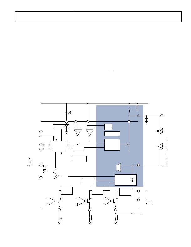
Figure 25. Detailed Block Diagram
Rev. B | Page 13 of 24
发布紧急采购,3分钟左右您将得到回复。
相关PDF资料
ADP1712-EVALZ
BOARD EVALUATION ADP1712
ADP1720-EVALZ
BOARD EVAL FOR ADP1720-ADJ
ADP2140CPZ-REDYKIT
REDYKIT 2 BOARDS ADP2140ACPZ
ADP3110AKRZ-RL
IC MOSFET DRIVER DUAL 12V 8SOIC
ADP3120AJCPZ-RL
IC MOSFET DRIVER DUAL 12V 8-DFN
ADP3121JRZ-RL
IC MOSFET DRIVER DUAL 12V 8SOIC
ADP3415LRMZ-REEL
IC MOSFET DVR DUAL BOOTST 10MSOP
ADP3419JRM-REEL
IC MOSFET DVR DUAL BOOTST 10MSOP
相关代理商/技术参数
ADP1653ACPZ-R71
制造商:AD 制造商全称:Analog Devices 功能描述:Compact, High Efficiency, High Power Flash/Torch LED Driver with Dual Interface
ADP1653-EVALZ1
制造商:AD 制造商全称:Analog Devices 功能描述:Compact, High Efficiency, High Power Flash/Torch LED Driver with Dual Interface
ADP1655
制造商:AD 制造商全称:Analog Devices 功能描述:Dual LED Flash Driver with I2C-Compatible Interface
ADP16550001ACBZR
制造商:Analog Devices 功能描述:
ADP1655ACBZ-R7
功能描述:IC LED DRVR BKLGT FLASH 12-WLCSP RoHS:是 类别:集成电路 (IC) >> PMIC - LED 驱动器 系列:- 标准包装:6,000 系列:- 恒定电流:- 恒定电压:- 拓扑:开路漏极,PWM 输出数:4 内部驱动器:是 类型 - 主要:LED 闪烁器 类型 - 次要:- 频率:400kHz 电源电压:2.3 V ~ 5.5 V 输出电压:- 安装类型:表面贴装 封装/外壳:8-VFDFN 裸露焊盘 供应商设备封装:8-HVSON 包装:带卷 (TR) 工作温度:-40°C ~ 85°C 其它名称:935286881118PCA9553TK/02-TPCA9553TK/02-T-ND
ADP1655-EVALZ
功能描述:BOARD EVAL ADP1655 RoHS:是 类别:编程器,开发系统 >> 评估板 - LED 驱动器 系列:- 标准包装:1 系列:PowerWise® 电流 - 输出 / 通道:20mA 输出及类型:1,非隔离 输出电压:17V 特点:可调光 输入电压:2.7 ~ 5.5 V 已供物品:板 已用 IC / 零件:LM3508 相关产品:LM3508TLX-ND - IC LED DRVR WHT BCKLGT 9USMDLM3508TLDKR-ND - IC LED DRVR WHT BCKLGT 9MICROSMDLM3508TLCT-ND - IC LED DRVR WHT BCKLGT 9MICROSMDLM3508TLTR-ND - IC LED DRVR WHT BCKLGT 9MICROSMD
ADP165ACBZ-1.2-R7
功能描述:Linear Voltage Regulator IC Positive Fixed 1 Output 1.2V 150mA 4-WLCSP (0.97x0.97) 制造商:analog devices inc. 系列:- 包装:带卷(TR) 零件状态:有效 稳压器拓扑:正,固定式 电压 - 输出:1.2V 电流 - 输出:150mA 电压 - 跌落(典型值):- 稳压器数:1 电压 - 输入:2.2 V ~ 5.5 V 电流 - 限制(最小值):215mA 工作温度:-40°C ~ 125°C 安装类型:表面贴装 封装/外壳:4-UFBGA,WLCSP 供应商器件封装:4-WLCSP(0.97x0.97) 标准包装:3,000
ADP165ACBZ-1.8-R7
功能描述:Linear Voltage Regulator IC Positive Fixed 1 Output 1.8V 150mA 4-WLCSP (0.97x0.97) 制造商:analog devices inc. 系列:- 包装:带卷(TR) 零件状态:有效 稳压器拓扑:正,固定式 电压 - 输出:1.8V 电流 - 输出:150mA 电压 - 跌落(典型值):- 稳压器数:1 电压 - 输入:2.2 V ~ 5.5 V 电流 - 限制(最小值):215mA 工作温度:-40°C ~ 125°C 安装类型:表面贴装 封装/外壳:4-UFBGA,WLCSP 供应商器件封装:4-WLCSP(0.97x0.97) 标准包装:3,000
